
luni, 31 decembrie 2012
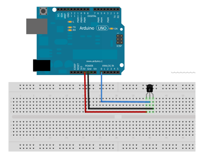
My present project, C# interfacing with Arduino
Bidirectional serial communication between C # and Arduino.
Analog and digital communication, both at the same time.
I built the PCB around ATMEGA8.
I used a 16x2 LCD to check sent / received data.
I/O:
2 digital outputs (2 LEDs),
1 PWM output (1 DC motor),
2 digital inputs (2 switches),
2 analog inputs (1 potentiometer and 1 phototransistor).


Watch video:
C# communicate with Arduino Part.1

We have 3 buttons that help turn on / off 3 LED.

The first push of the green button turns ON green LED, the second push of the green buttonturns OFF green LED. Is the same for the rest of the buttons.
C# code:
using System;
using System.Collections.Generic;
using System.ComponentModel;
using System.Data;
using System.Drawing;
using System.Linq;
using System.Text;
using System.Windows.Forms;
using System.IO.Ports;
namespace SERIAL_DIGITAL_WRITE
{
public partial class Form1 : Form
{
int green=0;
int blue=0;
int red=0;
public Form1()
{
InitializeComponent();
}
private void button1_Click(object sender, EventArgs e)
{
serialPort1.Open();
if (green==0)
{
serialPort1.Write("1");
green = 1;
}
else if (green == 1)
{
serialPort1.Write("2");
green = 0;
}
serialPort1.Close();
}
private void button2_Click(object sender, EventArgs e)
{
serialPort1.Open();
if (blue == 0)
{
serialPort1.Write("3");
blue = 1;
}
else if (blue == 1)
{
serialPort1.Write("4");
blue = 0;
}
serialPort1.Close();
}
private void button3_Click(object sender, EventArgs e)
{
serialPort1.Open();
if (red == 0)
{
serialPort1.Write("5");
red = 1;
}
else if (red == 1)
{
serialPort1.Write("6");
red = 0;
}
serialPort1.Close();
}
}
}
Arduino code:
///----------------------------------------///
/// by gabimincu 31.12.2012 ///
/// testing serial digital write ///
/// gabimincu@gmail.com ///
/// www.robot-fun.blogspot.com ///
///----------------------------------------///
int green = 4; // using pin 4 for the GREEN LED
int blue = 3; // using pin 4 for the BLUE LED
int red = 2; // using pin 4 for the RED LED
int i;
int data = 222;
void setup()
{
Serial.begin(9600); // Opens serial port, sets data rate to 9600 bps
pinMode(green, OUTPUT); // sets pin as output for green led
pinMode(blue, OUTPUT); // sets pin as output for blue led
pinMode(red, OUTPUT); // sets pin as output for red led
for (i=0;i<5;i++) // it shows that programs works
{
digitalWrite(green,HIGH);
delay(44);
digitalWrite(blue,HIGH);
delay(44);
digitalWrite(red,HIGH);
delay(44);
digitalWrite(green,LOW);
delay(44);
digitalWrite(blue,LOW);
delay(44);
digitalWrite(red,LOW);
delay(44);
}
}
void loop()
{
if (Serial.available() > 0)
{
data=Serial.read();
switch(data)
{
case '1':
digitalWrite(green, HIGH); // set the GREEN LED on
break;
case '2':
digitalWrite(green,LOW); // set the GREEN LED off
break;
case '3':
digitalWrite(blue, HIGH); // set the BLUE LED on
break;
case '4':
digitalWrite(blue,LOW); // set the BLUE LED off
break;
case '5':
digitalWrite(red, HIGH); // set the RED LED on
break;
case '6':
digitalWrite(red,LOW); // set the RED LED off
break;
}
}
}
Next time I will try to illustrate analog read from C# application.
sâmbătă, 29 decembrie 2012

marți, 27 noiembrie 2012

.png)

marți, 19 iunie 2012


sâmbătă, 12 mai 2012
Ultrasound Measurement Device - part.1
Work in progress...
The objective of this work is to design and manufacture a machine to measure distances using an ultrasonic sensor. Because sound speed variation with temperature, will be implemented and a temperature sensor, which will increase measurement accuracy.
The objective of this work is to design and manufacture a machine to measure distances using an ultrasonic sensor. Because sound speed variation with temperature, will be implemented and a temperature sensor, which will increase measurement accuracy.
The schematics:


The components:
IC1 – ATMEGA8,
IC2 – LM7805,
D1 – 1N4004,
C6,C7 – 47uF,
C2,C3 – 22pF,
C1,C4,C5,C8,C9,C12 – 100nF,
R1,R4 – 10K,
R2 – 330R,
R3 – 220R,
R7 – 1K,
Trimmer 10K,
Q1 – 16MHz,
L1,L2 – Led,


///----------------------------------------///
/// by gabimincu 10.05.2012 ///
/// masurarea distantelor cu ultrasunete ///
/// gabimincu@gmail.com ///
/// www.robot-fun.blogspot.com ///
///----------------------------------------///
#include <LiquidCrystal.h>
LiquidCrystal lcd(12, 11, 5, 4, 3, 2);
const int pingPin = 7; // pin trig senzor
const int inPin = 9; // pin echo senzor
int t=0;
int i;
float tempc = 0,temp; //variabile temperatura
int d;
float durata,cm; //variabile distanta
void setup()
{
Serial.begin(9600);
lcd.begin(16, 2);
pinMode(8,INPUT);
}
void loop()
{
afisare();
Do you want the rest of the code?
Next step: construction of box
marți, 17 aprilie 2012


duminică, 15 aprilie 2012
Almost ready...
Built with PIC 18F2550 from Microchip.
Future improvement: implementation of a steering control so you just turn to the desired angle.
For now this is my mobile robot:
This is the Pinguino with 18F2550 from Microchip:


This is DC motor controller which I have used.


..and the unipolar stepper controller:


And the code that I use it now:
#include
#include
const int pingPin = 7;
const int SafeDist = 40;
unsigned long duration;
long int cm,st,dr;
int motorPin1=14;
int motorPin2=16;
int motorPin3=13;
int motorPin4=15;
int motorDelay=3;/// viteza stepper
int i;
void setup()
{
///pini motoare dc
pinMode (0,OUTPUT);
pinMode (1,OUTPUT);
pinMode (2,OUTPUT);
pinMode (3,OUTPUT);
///pini stepper bipolar
pinMode(13, OUTPUT);
pinMode(14, OUTPUT);
pinMode(15, OUTPUT);
pinMode(16, OUTPUT);
}
void SonarScan()
{
pinMode(pingPin, OUTPUT);
digitalWrite(pingPin, HIGH);
delayMicroseconds(5);
digitalWrite(pingPin, LOW);
pinMode(pingPin, INPUT);
duration = pulseIn(pingPin, HIGH,10000);
}
void inainte()
{
digitalWrite(0, HIGH);
digitalWrite(1, LOW);
digitalWrite(2, HIGH);
digitalWrite(3, LOW);
delay(200);
digitalWrite (0,LOW);
digitalWrite (1,LOW);
digitalWrite (2,LOW);
digitalWrite (3,LOW);
}
void ho()
{
digitalWrite(0, LOW);
digitalWrite(1, LOW);
digitalWrite(2, LOW);
digitalWrite(3, LOW);
}
void inapoi()
{
digitalWrite (0,LOW);
digitalWrite (1,HIGH);
digitalWrite (2,LOW);
digitalWrite (3,HIGH);
delay(1000);
digitalWrite (0,LOW);
digitalWrite (1,LOW);
digitalWrite (2,LOW);
digitalWrite (3,LOW);
}
void dreapta()
{
digitalWrite (0,HIGH);
digitalWrite (1,LOW);
digitalWrite (2,LOW);
digitalWrite (3,HIGH);
delay(666);
digitalWrite (0,LOW);
digitalWrite (1,LOW);
digitalWrite (2,LOW);
digitalWrite (3,LOW);
}
void stanga()
{
digitalWrite (0,LOW);
digitalWrite (1,HIGH);
digitalWrite (2,HIGH);
digitalWrite (3,LOW);
delay(666);
digitalWrite (0,LOW);
digitalWrite (1,LOW);
digitalWrite (2,LOW);
digitalWrite (3,LOW);
}
///baleere stanga
void bast()
{
for(i=1;i<130;i++)
{
digitalWrite(motorPin1, HIGH);
digitalWrite(motorPin2, LOW);
digitalWrite(motorPin3, HIGH);
digitalWrite(motorPin4, LOW);
delay(motorDelay);
digitalWrite(motorPin1, HIGH);
digitalWrite(motorPin2, LOW);
digitalWrite(motorPin3, LOW);
digitalWrite(motorPin4, HIGH);
delay(motorDelay);
digitalWrite(motorPin1, LOW);
digitalWrite(motorPin2, HIGH);
digitalWrite(motorPin3, LOW);
digitalWrite(motorPin4, HIGH);
delay(motorDelay);
digitalWrite(motorPin1, LOW);
digitalWrite(motorPin2, HIGH);
digitalWrite(motorPin3, HIGH);
digitalWrite(motorPin4, LOW);
delay(motorDelay);
}
}
///baleere dreapta
void badr()
{
for(i=1;i<130;i++)
{
digitalWrite(motorPin4, HIGH);
digitalWrite(motorPin3, LOW);
digitalWrite(motorPin2, HIGH);
digitalWrite(motorPin1, LOW);
delay(motorDelay);
digitalWrite(motorPin4, HIGH);
digitalWrite(motorPin3, LOW);
digitalWrite(motorPin2, LOW);
digitalWrite(motorPin1, HIGH);
delay(motorDelay);
digitalWrite(motorPin4, LOW);
digitalWrite(motorPin3, HIGH);
digitalWrite(motorPin2, LOW);
digitalWrite(motorPin1, HIGH);
delay(motorDelay);
digitalWrite(motorPin4, LOW);
digitalWrite(motorPin3, HIGH);
digitalWrite(motorPin2, HIGH);
digitalWrite(motorPin1, LOW);
delay(motorDelay);
}
}
void loop()
{
SonarScan();
if (duration < 2000)
{
ho();
duration=0;
delay(300);
badr();
SonarScan();
dr=duration;
bast();
bast();
SonarScan();
badr();
st= duration;
if (dr< 2000 && st <2000)
{
inapoi();
stanga();
delay(55);
stanga();
}
else if (dr > st)
{
dreapta();
}
else stanga();
}
else inainte();
}
luni, 2 aprilie 2012
miercuri, 28 martie 2012


Pinguino 4550


Pinguino este o placa similara Arduino pe un microcontroler PIC4550.
Avantajul major fata de pinguino 2550 este ca are 10 pini suplimentari.
PS.
Bineinteles ca am uitat ceva cand am proiectat cablajul :)) ledul power.
O sa refac cand am timp.
luni, 5 martie 2012

sâmbătă, 3 martie 2012

My first Project at UPG
This was my first project. Made six months ago at UPG Ploiesti.

I worked with four other colleagues, guided by the computer architecture teacher.

The operating principle is based on pulling the film through the scanner, scan a video segment, then pulling back ...
I used a stepper motor from an old flopy 5.25 ".

My source of inspiration:
Abonați-vă la:
Comentarii (Atom)